Windy Selfsteering


Tough, strong and reliable self steering
New Windy coming soon
Model Windy (servo-pendulum, currently not available) feedback and nice blog:
Sailblog Yacht Flirtie, Voyager 40 Blog1: https://www.sailblogs.com/member/distantdrummer/483079 Blog2: https://www.sailblogs.com/member/distantdrummer/483286 Blog3: https://www.sailblogs.com/member/distantdrummer/
About ProVane
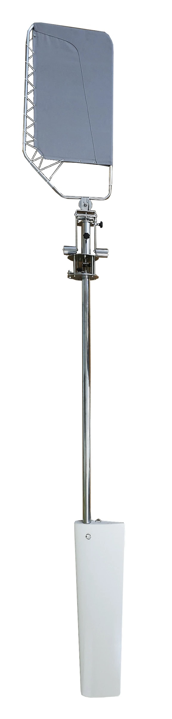
ProVane is designed for a larger boat with wheel (also suits for tiller) and it has emergency rudder ability. ProVane can be mounted off-center.
It’s rudder is 300x1100mm and also the windvane is large, 520x1000mm. ProVane is stand alone system, auxiliary rudder type, no steering lines in cocpit for the wheel.
Advantages over electric autopilots:
- It does not require electricity for its operation.
- Robust and simple construction.
- Emergency rudder with tiller.
- Vessels rudder system does not wear on longer trips.
Dimensions PDF:
proVane dimensions
For better understanding user manual is downloadable by this link here (Google Drive):
Photos and videos
Take a closer look at our product
Make your sailing experience more enjoyable
Nb no new orders will take new orders in august. apologies.
Text goes here
Text goes here also
Selfsteering equipment idea was born while I was sailing around the world across three oceans on a 31-feet yacht.
On the last leg from South Africa to Cabo Verde, flight home being less than 4000 nm away, the old noname self steering gear broke down when a bigger breaker hit the yacht from the side.
This gave me a reason to start developing a new self steering system that would be stronger. The idea was to build the cheapest windvane on the market that would still keep its strength and quality. By now Windy windvane has successfully sailed across the Atlantic ocean many times.
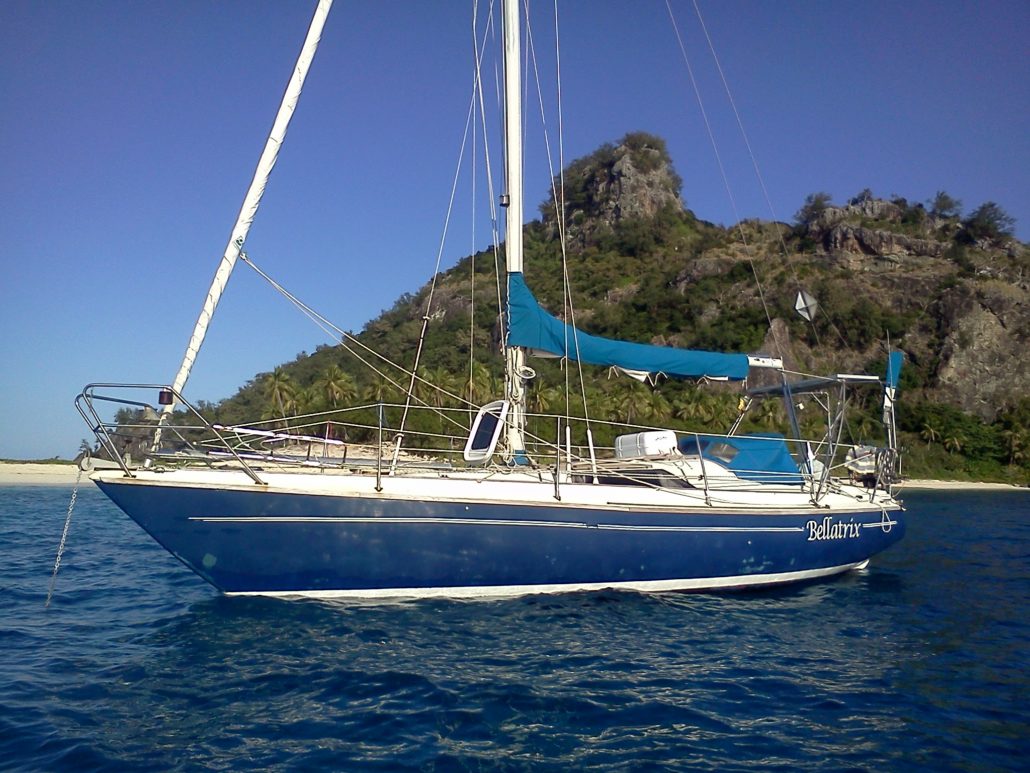
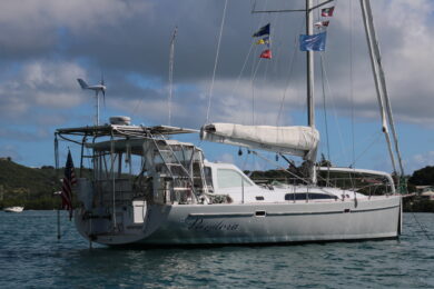
S/Y Bellatrix
Got a question?
Silber Metallic OÜ
Registry code: 11574431
Address: Köömne 18, Tallinn, Estonia 10617
E-mail: [email protected]
Phone and WhatsApp: +372 5667 6656
Send us a message
- Masting, rigging and sails

- Remember me Not recommended on shared computers
Forgot your password?
Pond Yacht rigging
By JerseyCity Frankie May 3, 2015 in Masting, rigging and sails
- Reply to this topic
- Start new topic
Recommended Posts
Jerseycity frankie.
Im sifting the internet looking for information about pre-radio control Pond yacht rigging. Working rigging for sailing scale models.
Before radio control, as I am sure all of you know, pond yachts reached a high degree of sophistication. Self tacking steering gear controlled by wind vanes, with a lot of complex brass hardware with elastic bands and adjustable sliders, were visible on deck and could be set by the user on shore to match the prevailing wind conditions and desired point of sail.
My problem is in finding authoritative information on these mechanisms. Nearly ALL of the images I find of historic Pond Yachts, those not in actual contemporary photos, are of models that have been restored and have had their steering gear simplified, presumably by antique dealers with little working sail understanding. In most of these cases its very obvious that brass fittings remaining on deck are not rigged in a way that would have an actual effect, they have merely been mocked up to look like they function and are often left unconnected to the sails.
Have any of you R.C. guys come across books or websites that deal with this aspect f the hobby? I hope there is a repository of this knowledge somewhere, it would be a shame to lose it.

- Omega1234 , Jack12477 , markjay and 3 others

Niagara USS Constitution
Link to comment
Share on other sites.
Blue Jacket Ship Crafters, in their book department sells two books on pond models. Both books are by M. de Lesseps. They are Pond Models and Pond Yachts How To Build And Sail Them. These books may have the information you're looking for.
Yowch $57 on Amazon! But I see only $21 at Blue Jacket. Thanks for the tip!
I wrote to the Central Park Yacht Club and they put me in touch with a gentleman with experience with the subject. I was touched by his generosity when he wrote back and sent along annotations on the photo I had sent him.
He explains that:
......... sheet-to-tiller rig: there were *two* mainsheets, one used on going to windward and the other on the run. Both typically had hooks on the end so they could be switched.
Sailing upwind, the boat sailed on balance only, tiller centered by the elastic as shown in the picture. The beating sheet ran from the end of the boom and was hooked on the ring on the main horse. Running sheet hung loose. On the run, the running sheet would be hooked to the tiller as shown, and run out so the main boom was swung out to one side or the other. The beating sheet would hang loose. The principle is that if the boom were swung to starboard, the boat would tend to turn to port. The pressure of the wind would pull on the main sheet against the elastic and give opposite helm to the rudder , thus guiding the boat. The jib would have a single sheet, adjusted with a tensioning device, let out for the run and pulled in for the beat.

- Omega1234 , Jack12477 , IgorSky and 2 others
- 2 weeks later...
Found this on Google books and it is relevant: https://books.google.com/books?id=_jYCAAAAQAAJ&pg=PA103&dq=Pond+Models+%C2%A0and+Pond+Yachts&hl=en&sa=X&ei=8NtZVbWuHq7IsQTHgYHADg&ved=0CC4Q6AEwAg#v=onepage&q=Pond%20Models%20%C2%A0and%20Pond%20Yachts&f=false
- 1 month later...
Try this web site from the UK: www.vmyg.uk. Its called the Vintage Model YachtGroup, its web site has a link to a
instruction book for various self steering mechanisms and how they work.
Looked interesting.
Bridgman Bob
Thanks for the link to the website! I thought I had seen them all by now but this was a new one to me. Here are some shots of the model I am restoring, one of two. THis example was likely not actually sailed. It has a lead keel but there is no rudder head, the rudder moves but does not pierce the deck.
The second model, not pictured, has rudimentary self steering gear and I will put up some photos of that later as I finish work on her.

I finished the restoration work I was doing on these two Pond Yacht Models. I have a new appreciation for this type of model and plan on building one of my own now. Here are some before and after photos. ANd then just some details shots.

- Omega1234 , markjay and mtaylor
- 7 months later...
However, did you notice that shipping at Blue Jacket starts at $50.00?

Huh? http://www.bluejacketinc.com/ordering.htm
Mark "The shipwright is slow, but the wood is patient." - me Current Build: Past Builds: La Belle Poule 1765 - French Frigate from ANCRE plans - ON HOLD Tri ton Cross-Section
NRG Hallf Hull Planking Kit HMS Sphinx 1775 - Vanguard Models - 1:64
Non-Ship Model: On hold, maybe forever:
CH-53 Sikorsky - 1:48 - Revell - Completed Licorne - 1755 from Hahn Plans (Scratch) Version 2.0 (Abandoned)
Join the conversation
You can post now and register later. If you have an account, sign in now to post with your account.

× Pasted as rich text. Paste as plain text instead
Only 75 emoji are allowed.
× Your link has been automatically embedded. Display as a link instead
× Your previous content has been restored. Clear editor
× You cannot paste images directly. Upload or insert images from URL.
- Insert image from URL
- Submit Reply
Recently Browsing 0 members
- No registered users viewing this page.
Modelshipworld - Advancing Ship Modeling through Research
SSL Secured
Your security is important for us so this Website is SSL-Secured
NRG Mailing Address
Nautical Research Guild 237 South Lincoln Street Westmont IL, 60559-1917
Model Ship World ® and the MSW logo are Registered Trademarks, and belong to the Nautical Research Guild (United States Patent and Trademark Office: No. 6,929,264 & No. 6,929,274, registered Dec. 20, 2022)
Helpful links.
- Articles Database
- NRG Home Page
- NRG Online Store
- Important: Our Guidelines
- Terms of Use
- Buildlog Index
About the NRG
If you enjoy building ship models that are historically accurate as well as beautiful, then The Nautical Research Guild (NRG) is just right for you.
The Guild is a non-profit educational organization whose mission is to “Advance Ship Modeling Through Research”. We provide support to our members in their efforts to raise the quality of their model ships.
The Nautical Research Guild has published our world-renowned quarterly magazine, The Nautical Research Journal, since 1955. The pages of the Journal are full of articles by accomplished ship modelers who show you how they create those exquisite details on their models, and by maritime historians who show you the correct details to build. The Journal is available in both print and digital editions. Go to the NRG web site (www.thenrg.org) to download a complimentary digital copy of the Journal. The NRG also publishes plan sets, books and compilations of back issues of the Journal and the former Ships in Scale and Model Ship Builder magazines.
Our Emblem ®
Nautical Research Guild ® and the NRG logo are Registered Trademarks, and belong to the Nautical Research Guild (United States Patent and Trademark Office: No. 6,999,236 & No. 6,999,237, registered March 14, 2023)
- Existing user? Sign In
- Latest Posts
- All unread content since my last vist
- Unread topics I have posted in
- Create New...
The home of the worlds best R/C Model Aircraft Designers
UK Manufactured to order: Guaranteed Quality
Products search
Login FAQ
[email protected] +44 (0)1684 311682
- Unorthodox Aircraft
- X-List Plans (Aircraft)
- F/F Sport & Competition
- C/L Aerobatic
- Round The Pole
- Brian Taylor
- Dennis Bryant
- Chris Golds
- Duncan Hutson
- Chris Williams
- Dave Hurrell
- Philip Noel
- Peter Miller
- Sepp Uiberlacher
- RCM&E Magazine Designs
- All Aircraft Plans not yet categorised
- All Short Kit (Sets)
- Scale Short Kit (Sets)
- Sport Short Kit (Sets)
- Depron Short Kit (Sets)
- All Laser Cut Wood Packs
- Scale Laser Cut Wood Packs
- Sport Laser Cut Wood Packs
- All Additional Wood Packs
- Scale Additional Wood Packs
- Sport Additional Wood Packs
- Private & Trainer aircraft
- Transport Aircraft
- WW1 Aircraft
- WW2 Aircraft
- JetWorks - Semi-Scale Park Jets
- Static Aircraft Wood Kits
- All Aircraft Parts
- ABS Sets & Fairing
- Cowls & Nacelles
- Intakes & Rads
- Spats & Undercarriage
- Spinners & Prop Nuts
- Cliff Charlesworth Cowls
- All Canopies & Screens
- Cliff Charlesworth Canopies
- Jilles Smits Canopies
- Pat Teakle Canopies
- Guns, Sights & Cockpits
- All Materials
- Depron Foam
- All Covering & Tools
- DiaCov 1000 Covering
- Lightweight Tissue
- Rotary Tools
- All Perma-Grit Tools
- Sanding & Filing Tools
- Cutting Tools
- Screwdrivers
- Hex Wrenches
- Clamps & Pliers
- Marking & Measuring
- Model Aircraft Covering
- Airbrushing
- Lighting & Magnification
- RTF Aircraft
- ARTF Aircraft
- Free Flight
- Books & Specials
- DVDs & Blu-Ray
- Bargain Aircraft DVDs SAVE!
- Full Size Focus CD
- Line Drawings
- Model Aircraft Magazine Plans
- Cabin Cruisers
- Coastal Forces
- Fishing Boats
- Paddle Steamers
- Leisure Craft
- Scale Traditional Craft - British Isles
- Merchant Vessels
- Scale Traditional Craft - Non British Isles
- Passenger Ferries
- Steam Designs
- Patrol Launch
- Rescue & Lifeboats
- Working Boats & Ships
- Traditional Craft - British Isles
- Traditional Craft - Non British Isles
- Racing Sailing Boats
- Sport Sailing Boats & Yachts
- Scale Sailing Boats & Yachts
- Competition Powerboats
- Competition Powerboats - IC
- Competition Powerboats - Electric
- Easy to Build Boats
- Engineering
- Hydroplanes
- X-List Plans (Boats)
- All other Boat Plans & not yet categorised
- All Plan & Hull Sets
- Sailing Plan & Hull Sets
- Motor Boat Plan & Hull Sets
- David Alderton Plan & Hull Sets
- All Boat Short Kit (Sets)
- Sailing Short Kit (Sets)
- Motor Boat Short Kit (Sets)
- RC Boat Kits
- All Static Model Boats
- Narrow Static Boats
- Motor/Steam Static Boats
- Sailing Static Boats
- Working Static Boats
- Ready To Run Model Boats
- All Boat Laser Cut Wood Packs
- Sailing Laser Cut Wood Packs
- Motor Laser Cut Wood Packs
- Sailing Additional Wood Packs
- Motor Additional Wood Packs
- All Boat Additional Wood Packs
- Hulls (FG & ABS)
- Boat Fittings
- Electronics (Boats)
- Plastic Materials & Parts
- Airbrushing (Boats)
- Rotary Tools (Boats)
- Internal Combustion Engines
- Steam Engines & Plant
- Workshop Equipment
- Model Railway Plans
- All Engineering Plans not yet categorised
- Military Vehicles
- OO Gauge Parts & Kits
- Scale Model Buildings
- O Gauge Parts & Kits
- Scale Model Boats
- HO Scale Parts
- Maintenance Trays
- White Metal Fittings
- Airbrushing (Engineering)
- Rotary Tools (Engineering)
- Engineering DVDs & Blu-Ray
- All Model Aircraft Covering
- DiaCov 1000
- Sanding & Filing
- Aircraft Books & Specials
- Aircraft DVDs & Blu-Ray
- Bargain DVDs SAVE!
- Boat Books & Specials
- Boat DVDs & Blu-Ray
- Books & Specials
- Chargers & Leads
- Control Boards & Accessories
- Hot-end Parts/Kits
- Motors/Drivers
- Teeth, Wheels & Bearings
- VORON Parts
- Automotive Parts
- Crafts & Games
- Electric Scooters
- Medical / Health
- Shot Glass Trays

30 years Experience
Of Scratch Building & Modelling The Home of the Model Builder

Made in our Workshop
Laser Cut & Printed to Order Guaranteed Quality & Detail

BRAINE AND VANE STEERING
Two sheets showing full working drawings for a variety of steering and sail control devices for vintage restored and replica yachts of all types.Most diagrams are fully dimensioned for reproduction by competent model makers.Designed by G W Clark.
SAVE 10% on Selected Plans!
£ 17.00 £ 15.30
Specification
Full description.
Featured in July 2001 Marine Modelling International
You must be logged in to post a review.
- 5 stars( 0 )
- 4 stars( 0 )
- 3 stars( 0 )
- 2 stars( 0 )
- 1 star( 0 )
- BOAT OF THE YEAR
- Newsletters
- Sailboat Reviews
- Boating Safety
- Sails and Rigging
- Maintenance
- Sailing Totem
- Sailor & Galley
- Living Aboard
- Destinations
- Gear & Electronics
- Charter Resources
- Ultimate Boat Giveaway
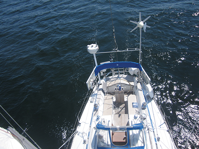
Self-Steering—with No Strings Attached
- By Darrell Nicholson
- Updated: February 4, 2002
C02DN01.jpg
Although servo-pendulum windvanes, which we covered last month (“Sorting Out Self-Steering Options,” January), remain the most popular type of windvane self-steering system, other designs fill an important niche. Some sailors prefer the direct mechanical linkages–so there are no steering lines to the cockpit–that these other systems feature, and some boats simply wont work well with servo-pendulum designs.
The alternative designs fall into two categories: trim-tab systems, which work with the boats rudder, and auxiliary-rudder systems, which steer with their own built-in rudders. These windvanes feature the same three major components as the servo-pendulum designs we reviewed–sensor vane, underwater course-correction unit (servo-rudder), and linkages.
The servo-pendulum windvanes we reviewed use low-stretch lines led through blocks to connect a vanes powerful pendulum-rudder to the boats tiller, wheel, or steering quadrant. In the trim-tab and auxiliary-rudder systems well look at, the linkage to the boats rudder or auxiliary rudder is mechanical, an arrangement that avoids problems of excessive stretch, chafe, or incorrect tension but can introduce corrosion problems and linkages that have their own complications. For owners of center-cockpit boats, the direct linkage eliminates the need for long lines running across the afterdeck.
The boats that stand to gain the most from such systems are ones with hydraulic steering or with wheel steering having four or more turns between stops, ones with high freeboard, or ones that are otherwise incompatible–or less compatible–with servo-pendulum steering vanes. In most other cases, servo-pendulum vanes offer undeniable advantages.
Trim Tabs Like the flap on an airplane wing, a trim tab is the trailing edge of a larger foil–in our case, either the ship’s primary rudder or an auxiliary rudder. When directed by the vane sensor, the trim tab turns. As long as the boat is moving fast enough, the lift provided by the change in water flow provides the force necessary to move the larger rudder. A trim tab should be balanced (meaning that its leading edge is forward of its axis of rotation), so that it’s easily driven by the vane sensor, and appropriately sized, so it provides sufficient power to control the rudder. Friction at its pintles and gudgeons should always be minimal.
Few of the trim-tab units we’ll review can be lifted easily out of the water or quickly removed from the rudder, a common shortcoming among both trim-tab and auxiliary-rudder systems. This not only makes the underwater unit more difficult to maintain and more vulnerable to damage, corrosion, and fouling; it also can add an unexpected twist when backing a boat under power. The biggest drawback of a traditional trim tab is that it can’t produce the same amount of power as a pendulum rudder of the same size, so a boat’s sail trim and helm balance become even more important. Heavy-displacement vessels with unbalanced rudders can make the trim tab’s job particularly tough. For emergency steering, you can use a trim-tab system that connects to the main rudder as long as the rudder to which it’s attached is intact and is still capable of turning (as in the case of a broken steering cable, for example).
Sayes Rig: The Sayes Rig is one of the few production windvanes that still uses a flag- type vertical-axis vane sensor, which functions like a masthead wind indicator, rotating so that its leading edge always points into the wind. A vertical-axis vane, however, cant generate as much force as a horizontal vane of the same size. Nevertheless, the Sayes Rig manages to provide an efficient steering impulse with a powerful wedge-shaped cloth vane. One reason the Sayes can get away with a relatively small vertical-axis vane is that the trim tab it commands is a very small, well-balanced, servo-pendulum rudder, which provides far more power than a conventional trim tab of the same size. The linkages are simple: The pendulum rudders shaft passes through an extended U-shaped tiller arm attached to the boats rudder. The longer tiller arm, the more power it provides, so it works best on boats with inboard rudders. The simple design allows for durable construction in 316 stainless steel and cast bronze.
Auto Steer: This system, made in England, is easily adapted to boats with outboard rudders. Through a simple acetal-plastic and silicon-bronze universal linkage, the horizontal-axis sensor vane connects to a custom-sized trim tab made of wood and stainless steel attached to the boats rudder. The Auto Steer trim-tab vane is made of LM25 aluminum castings and 316 stainless steel, with insulation between dissimilar metals to minimize galvanic action. The manufacturer, Hydra Engineering, doesnt recommend the system for heavy-displacement boats over 35 feet. For larger boats, the company makes a more powerful servo-pendulum unit.
Auxiliary Rudders An auxiliary rudder, because it’s smaller and often better balanced than the boat’s main rudder, reduces the resistance to the steering impulse, which, in the models we’ll look at, is delivered by either a trim tab, the vane sensor, or a servo-pendulum rudder. Because they operate independently of the boat’s rudder, auxiliary-rudder systems are compatible with hydraulic steering. They are also capable of serving, in a limited way, as an emergency rudder.
When selecting an auxiliary-rudder system, carefully consider proper rudder size and how it’s attached to the boat. Although the boat’s main rudder will be used to compensate for weather helm, the auxiliary rudder still needs to be powerful enough to steer the boat before a high quartering sea. Attachment points at the hull should be well reinforced, and the rudder shaft should be rugged. These details are particularly important if you need your auxiliary rudder to serve in an emergency. Heavy-displacement boats that are difficult to steer can test the limits of an auxiliary rudder that’s required to steer in an emergency. Auto-helm: This system features a large, wedge-shaped, horizontal-axis vane sensor made of 6061 T6 anodized aluminum that’s linked to a trim tab on an auxiliary rudder. The rudder mounts and underwater fittings are made of 316 stainless steel. The easily turned trim tab helps amplify the relatively weak wind impulse into a force that can drive the auxiliary rudder. The unique cable linkage (similar to a bicycle’s brake cables, but with smooth Teflon sheaths) between the sensor vane and the trim tab allows a great deal of flexibility in where you mount the vane. The vane can even be mounted on top of davits, which often interfere with other designs. These cables must be kept clean to ensure minimal friction. The sensor vane can also be used with a custom trim tab attached to an outboard rudder, in a manner similar to the Auto Steer system.
Hydrovane: This auxiliary-rudder system uses a horizontal-axis vane sensor to drive a well-balanced, solid-nylon rudder on a stainless-steel shaft. To accomplish this, the Hydrovane uses a relatively large sensor vane, a semibalanced rudder, and a variable ratio in the vane-to-rudder linkage. This adjustable linkage–with three separate positions for light, moderate, and heavy air–controls the mechanical advantage that the vane has over the rudder, or how far the auxiliary rudder will turn as the vane tilts. Another feature is an adjustable axis on the sensor vane, which allows you to further match the steering impulse to wave and wind conditions.
Construction of the Hydrovane unit is cast LM5 anodized aluminum, silicon bronze, and 316 stainless steel. An endless line to the vane allows you to position the vane relative to the wind from the safety of the cockpit. The Hydrovanes rudder can be easily centered for maneuvering in port or completely removed by simply pulling a pin.
Fleming Global Auxiliary Rudder: For boats that arent suited to its standard system, Fleming links its servo-pendulum windvane directly to an auxiliary rudder. Its auxiliary-rudder system uses the same high-quality stainless steel (2205 duplex-cast castings and 316 tubing) as the standard version we reviewed last month. It also carries the same array of stainless-steel bearings in Delrin races to reduce friction. An endless line led to the cockpit permits infinite course adjustment. Of the auxiliary-rudder systems we compared, the Fleming is the only one that has a hinged auxiliary rudder with overload protection. A shear pin offers impact protection, and the hinge makes it easy to lift the rudder out of the water. The servo rudder, which also has a shear pin for impact protection, easily swings out of the water–like the standard Fleming. You can also simply remove the servo-pendulum part of the system by undoing one bolt.
The linkage between the servo-pendulum rudder and the auxiliary rudder has a variable power ratio. This allows you to adjust how much rudder deflection there is for a given course error and lets you fine-tune steering characteristics to suit a variety of wind and sea conditions. A clutch system allows you to engage or disengage the servo blade under load.
Windpilot Pacific Plus: Windpilot takes its Pacific-series servo-pendulum vanes one step further by using a servo-pendulum system to drive an auxiliary rudder. The combined unit features the same construction details as the Pacific series: infinitely adjustable course setting, bevel-gear linkage between the vane and pendulum rudder, a lift-up pendulum rudder, and low-maintenance sleeve bearings. The body construction is high-grade AlMg5 aluminum-alloy castings. The linkage between the servo-pendulum and the auxiliary rudder is a bronze bevel gear thats easily disengaged. Although you can easily fold up the servo-rudder, the auxiliary rudder is designed to stay in the water. You can, however, quickly center the rudder when the servo-pendulum rudder is in the raised position.
Darrell Nicholson is a Cruising World associate editor.
- More: systems
- More How To

Made for Shade: Cockpit Cover Options

Blackwater Wisdom for Holding Tanks

5 DIY Basics For Your Diesel Engine

Unraveling Efficiency: Diesel vs. Electric Propulsion

Cruising Tahiti: A Party in Paradise

Sailboat Review: Fountaine Pajot Aura 51

Introducing Bitter End’s Beach Bungalows

Off Watch: School Daze
- Digital Edition
- Customer Service
- Privacy Policy
- Terms of Use
- Email Newsletters
- Cruising World
- Sailing World
- Salt Water Sportsman
- Sport Fishing
- Wakeboarding
- SAILOMAT 800
- SAILOMAT 760
- Designer's Comments
- Overall Description
- Main Features
- Technical Info
- Component Photos
- Installation Photos
- Questions and Answers
- Pricing Information
- User Comments
- Installation Examples
The ULTIMATE in Sailboat Self-Steering
SAILOMAT is the world's leading professional design team and manufacturer specializing in state-of-the-art mechanical self-steering systems for all cruising sailboats.
Universally acknowledged among world cruisers as the most advanced self-steering systems available – a SAILOMAT is a masterpiece of design and function. The very high strength, built-in simplicity, simple mounting, reliability, and long life make SAILOMAT Self-Steering the distinguished leader in its field.
The most recent design is the SAILOMAT 800/760/700 series, based on 40 years of self-steering design experiences , practical testing and manufacturing under the group leadership of Dr. Stellan Knöös, both in Sweden and USA. The state-of-the-art and innovative SAILOMAT 800 system represents the next generation in sailboat self-steering.
The Ultimate in Sailboat Mechanical Self-Steering Custom Design and Manufacturing Worldwide sales Factory Direct Since 1974. San Diego, California, United States www.sailomat.com [email protected]
Specifications
CONFIGURATION BY BOAT TYPE
This is a listing of some of the boats we have provided a Hydrovane for, showing the configuration used (Shaft Length, Upper Bracket, Lower Bracket). Please note that the same model boat does not necessarily use the same configuration – there are variables such as aerial obstructions and other boat-specific factors.
OVERALL DIMENSIONS
This schematic may be helpful for you to understand the fit requirements for the Hydrovane. We want to position the Hydrovane tiller at an appropriate height while also ensuring that the Vane has enough airspace. This schematic shows our Standard Vane.
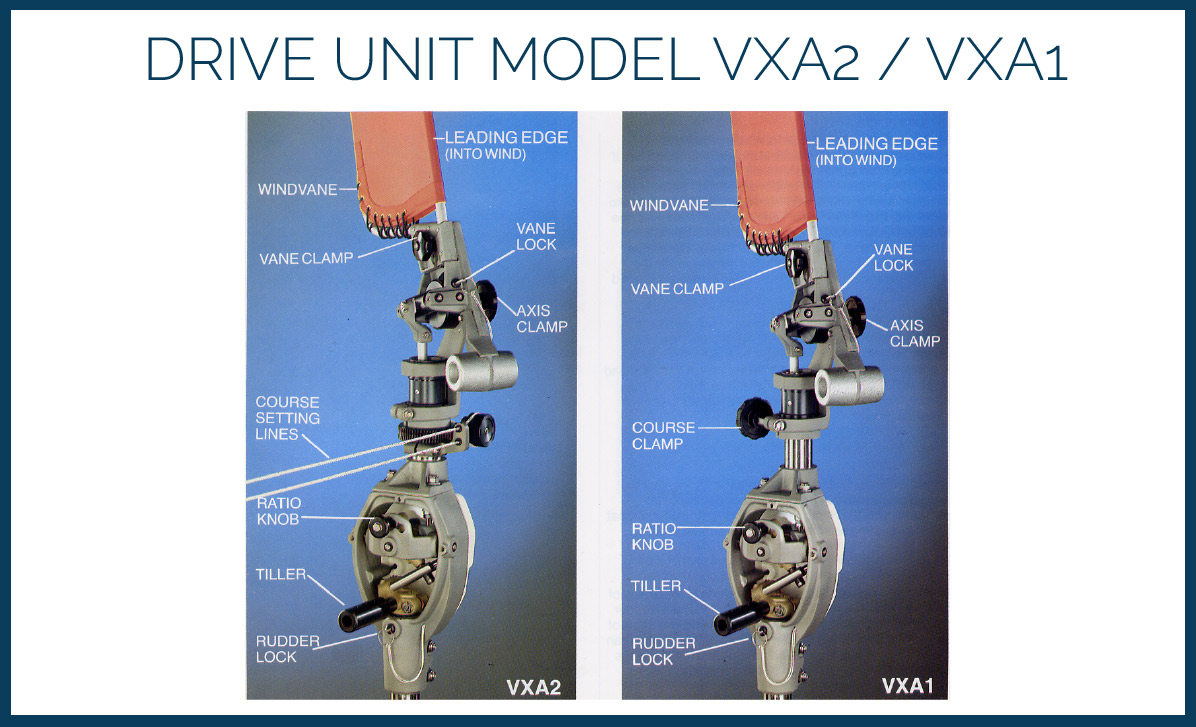
The Drive Unit
Today’s Drive Unit is the VXA1 / VXA2 Model.
Both are variations on the only model available today, and since 1986. The majority of Hydrovanes sold are the VXA2 model; the remote course setting capability is well worth it. A VXA1 may be suitable for a smaller cruising boat with an arm’s reach from the cockpit to the Course Control Knob.
The Drive Unit is where the magic happens… it is the sophisticated linkage mechanism that multiplies the forces on the vane by many times.
The Shaft Assembly
The Hydrovane shaft assembly includes the shaft, the outer tube, and shaft bearings.
Older units: The shaft outer diameter will be either 1 1/8 in (28.575 mm) – out of production since 2002 – or 1 ¼ in (31.75 mm).
Since early 2009, all shafts are made of solid 1 ¼ in Ferrinox 225 ‘Super Duplex’ stainless steel – three times as strong as ‘316’.
All shafts are machined to 1 in (25.4 mm) at the top.
The tube has a 2″ outer diameter.
Shaft Required
The length required depends on the stern height, and if there are any aerial obstructions. The table below shows the required shaft length, assuming that for free vane movement the stern rail is not more than 24 in (610 mm) above the deck and does not project aft of the stern. Otherwise, the next longer shaft may be needed.
| S-5, S-10 | <34 in (<860 mm) | |
| S – Short | 34 in (860 mm) | |
| M – Medium | 43 in (1090 mm) | |
| L – Long | 53 in (1340 mm) | |
| X – Extra Long | 63 in (1600 mm) | |
| X+5, X+10, etc. (in) | As required |
Shaft Lengths
These measurements are from tip to tip of the inner shaft. When the Drive Unit is fitted onto the shaft, about 8 inches (203 mm) of the shaft assembly is covered.
*In 2018 we added an extra 3mm to the top of the shaft (the part that is machined to 1″ OD). Below are the original tip to tip measurements.
| S – Short | 38 9/16 in (979 mm) |
| M – Medium | 47 9/16 in (1208 mm) |
| L – Long | 57 9/16 in (1462 mm) |
| X – Extra Long | 67 9/16 in (1716 mm) |
| X+5 | 72 9/16 in (1843 mm) |
| X+10 | 77 9/16 in (1970 mm) |
| X+20 | 87 9/16 in (2224 mm) |

The Hydrovane vane needs a lot of airspace – can be as tall as 12 ft / 4m above the water and more importantly it has a lateral reach of over 4 ft / 120 cm. in all directions at that height – yes, a full 360 degrees!
If your boat has:
- Bimini that reaches aft
- Arch supporting solar panels or communication gear
- Radar post/mast
- Wind Generator
- Any other aerial obstacles but not davits (normally are low enough)
…then we need photos taken at 90 degrees to the transom and from dead aft – showing from the water to the top of those obstacles – in order to properly configure an installation.
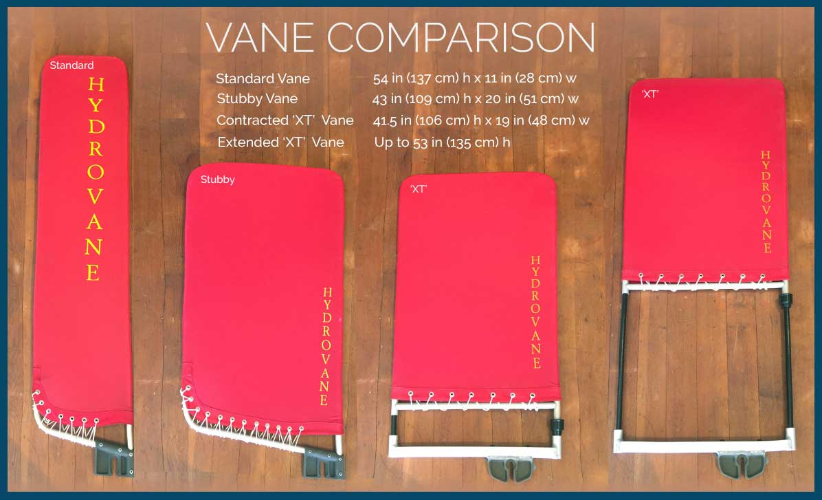
Boats with any of the above aerial obstructions often use the Stubby Vane.
Our newest Vane – the Extendable ‘XT’ vane – has many benefits, including more leverage/power, and the ability to be ‘reefed’ in heavy weather or on a certain point of sail if there is an aerial obstruction.
THE Brackets
Every installation requires two brackets – a combination of the three brackets we manufacture. The brackets required are entirely dependent on the transom of your boat.
H ‘Hinged’ Bracket
Every installation must have at least one H Bracket. The ‘H’ bracket is located at about the closest point from the shaft to the stern.
E ‘Elbow’ Bracket
This is the single strut bracket. It can be more difficult to install, but is less expensive than the A bracket.
- It is the only bracket without a hinge, meaning the angles are fixed and must be accommodated by using timber pad(s) to accommodate the contour of the hull and the difference in angles.
- Fixed Angles – Each of the castings at either end of the Strut (Stay Tube) hold the tube at an angle of 15 degrees. The result, depending on the direction the castings are positioned, creates aggregate angles of either 30 (15 + 15) or zero (15 – 15) degrees.
- The Strut is provided at a maximum length of 18”, to be cut down to required length.
A ‘Double Strut’ Bracket
The A bracket is our biggest, strongest, and most versatile bracket. The A bracket solves the most difficult installation issues.
- Arms swing up or down vertically
- Arms open in or out from 40 to 80 degree separation (as of summer 2013 – prior model fixed at 40 degrees)
- Transom attachment flanges fully rotate to become flush with any surface.
- Strength – Engineers love triangles
- Struts/tubes can be cut to any length. Struts are provided at 31”, to be cut down as necessary. Some installations require even longer tubes, which we can provide.

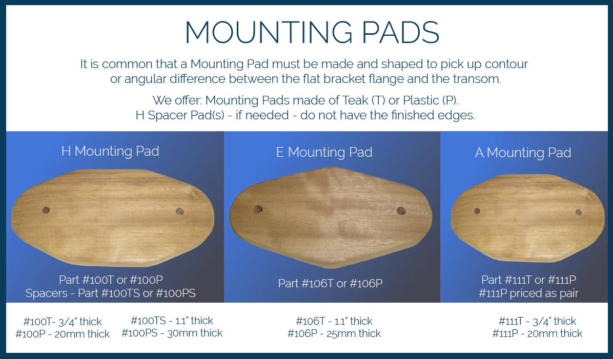
Mounting Pads
A Mounting Pad is a shaped piece of non-ferrous material (often teak wood or a synthetic like G10 Micarta or High Density Polyethylene – HDPE – is used) that is fitted between the bracket flanges and the transom. The Mounting Pad is fashioned or shaped to pick up any contour differences between the flat flange face and the transom.
Mounting Pads may not be necessary for your installation – if the transom is perfectly flat.
We offer Mounting Pads in either Timber (teak) or Plastic (HDPE).
Making and shaping the pads can often be the most difficult part of the installation. If you choose to make your own, please find the templates below.
For shaping the pads, read the tips in our Installation Guide.
MORE INFORMATION
Helpful measurements.
- H bracket creates a distance from shaft to transom of between 1.5 in (3.8 cm) to 4.5 in (11 cm)
- The minimum distance required for an E bracket is 8in (20 cm)
- The minimum distance required for an A bracket is 16in (40 cm)
- The maximum exposed shaft between the top bracket and the drive unit is 18 in (46 cm)
- Space, distance between the bottom bracket and the bottom bearing: between 2 in and 10 in (5 cm and 25 cm)
- The minimum separation between the two rudders should be 8in (20 cm)
- Lighter – 66 lbs (30 kg) – S/H/H
- Average – 83 lbs (37 kg) – L/E/H
- Heavier – 113 lbs (51 kg) – X/A/H
- Shafts, axles and fastenings: 316 (EN58J) stainless steel except the main shaft which is Ferrinox 255 (Super Duplex), solid stainless
- Castings: LM25 anodized aluminum alloy and silicon bronze
- Bearings: Glass Filled PET, PFTE and Acetal (Delrin). Nylon ball race on rudder shaft.
- Rudder: Solid N6 nylon casting. Tapered NACA profile
- Wind Vane: Reinforced nylon cloth (ripstop) on anodized alloy tube frame
- Course control: 4 in (100 mm) oilon worm gear
Weather Forecast
2:00 pm, 06/12: -11°C - Partly Cloudy
2:00 am, 07/12: -4°C - Clear
2:00 pm, 07/12: -7°C - Partly Cloudy
2:00 am, 08/12: -3°C - Overcast
- Cruising Compass
- Multihulls Today
- Advertising & Rates
- Author Guidelines
British Builder Southerly Yachts Saved by New Owners

Introducing the New Twin-Keel, Deck Saloon Sirius 40DS

New 2024 Bavaria C50 Tour with Yacht Broker Ian Van Tuyl
Annapolis Sailboat Show 2023: 19 New Multihulls Previewed

2023 Newport International Boat Show Starts Today
Notes From the Annapolis Sailboat Show 2022
Energy Afloat: Lithium, Solar and Wind Are the Perfect Combination

Anatomy of a Tragedy at Sea
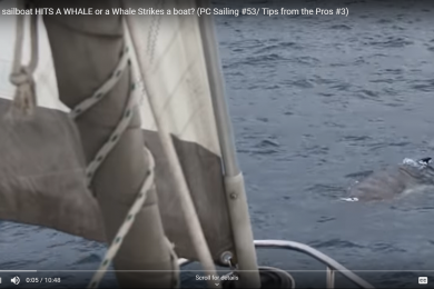
What if a Sailboat Hits a Whale?!?

Update on the Bitter End Yacht Club, Virgin Gorda, BVI

Charter in Puerto Rico. Enjoy Amazing Food, Music and Culture

With Charter Season Ahead, What’s Up in the BVI?
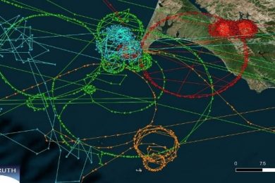
AIS Mystery: Ships Displaced and Strangely Circling
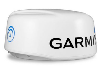
Holiday Sales. Garmin Marine Stuff up to 20% Off
- Blue Water Sailing
Choosing and Understanding Self-Steering Gear
A guide to equipping your boat with an electronic autopilot or windvane: Part I (published October 2013)
Since the earliest days of long-distance solo or shorthanded sailing, a variety of devices have been invented for holding a boat on her course without the need of a constant helmsman. One of the early—and for many boats, still useful—methods was called “sheet-to-tiller” steering, which balanced the forces on a mainsail’s sheet against a spring or shock cord to steer the tiller in the appropriate direction when the boat would heel and reverse the direction when she would start to round up. This is obviously a delicate balance that required careful and often time-consuming readjustment when a course change or wind shift occurred.
Along with sheet-to-tiller steering came windvanes, which use a variety of methods to transfer a course change into a rudder angle using various paddles or vanes attached at the stern of the boat. Then, with the dawning of reliable electronics came motor-driven electric “autopilots” with a variety of methods for operation and all with the requirement for electric power and various instrumentation sources.
Today, a dizzying array of self-steering gear exists and it’s often difficult to know where to start. Some kits costs more than a small boat, and others can be made or cobbled together from spare parts in a garage. But by understanding the principles, major options, advantages and caveats of the various gear on the market, a prudent skipper can choose the right self-steering gear for his or her boat with confidence, knowing it will suit the boat in all conditions.
MAJOR CONSIDERATIONS The major questions and choices when faced with the purchase of new self-steering gear are: What conditions the unit is expected to perform in; what are the possible failure modes, how to recover from them, and how to detect or prevent them when underway; whether to get an electronic unit, windvane or both; where to mount the components and how to attach them to the boat; and last but not least, how much should ongoing maintenance and the expected service life of the gear be considered?
I’ve listed the options in this order because the most important thing about self-steering gear is whether or not it suits the conditions it is expected to operate in, including whether or not it is a good match for the vessel. The decision between an electronic autopilot and a windvane can only be made when a skipper decides these other issues first. After that, the decision becomes a technical one between models and options.
In order to help the skipper understand which equipment makes a good match for what conditions and vessel, it’s helpful to go into some detail on the various components and options available. So in this first of two articles on the topic, let’s dive more deeply into the realm of the electronic autopilot.
WHY CHOOSE AN ELECTRONIC AUTOPILOT? Since ships started installing electrical equipment onboard, the electronic autopilot has become a go-to self-steering device for both sailors and powerboaters alike. Combined with an electric or optical compass, all an autopilot needs to keep a boat on a constant magnetic heading is electric power. With the advent of data networks aboard, wind and GPS instrumentation can be combined with the autopilot to steer to waypoints, maintain a constant wind angle like a wind vane, steer specific patterns in the sea (e.g. circles, grids, or holding position for fishing or search-and-rescue), and perform many other clever tricks that a simple wind vane cannot do. And, of course, the electronic autopilot can do all of this whether or not the wind is blowing. As a result, electronic autopilots are nearly ubiquitous on most modern sailboats.
Electronic autopilots require three main components: a drive unit, a compass—usually called a “fluxgate compass” or for short, “fluxgate”—and a processing module, or “brain”. The processing module may or may not require a separate display and control interface, or it may incorporate it directly, and any or all of these components may be included in the same physical device. Make sure your autopilot package includes all of them though, or you may have to spend significantly more money later.
There are two major categories of electronic autopilots and quite a variety of options within those categories. The differences are crucial to your boat and to the system’s reliability, so it pays to at least take a cursory glance at some of these important details.
TILLER AND WHEEL PILOTS The most common category on small boats, a tiller or wheel pilot is an electronic motor attached to either a sliding lever or a spinning gear that is connected to the ship’s own tiller or wheel to physically move the boat’s rudder. Simple to install and easy to understand, these are typically the least expensive devices and are usually only reliable up to a certain amount of rough sea conditions, after which they often don’t have the power to keep handling the helm. In addition, they are constantly exposed to salt spray, and attachment and dismounting results in a certain amount of wear and tear over time. However, they are simple to understand and use and for smaller boats are often perfectly sufficient as long as the expectations on the system are reasonable. There are a few wheel units these days that have been used with success in heavy seas offshore, but they are rare and require a well balanced or easily helmed boat and are subject to limitations on rudder size and force.
Tiller and wheel pilots often, but not always, integrate the processing module and the drive unit in the same housing, simplifying use even further. They do not, however, offer anything in the way of redundancy over and above a ship’s own steering system, as they are dependent on that very system to perform their job.
Often, a skipper will fit a tiller or wheel pilot as a backup to a windvane when they decide that a wind vane is most suitable for their vessel.
BELOWDECKS PILOTS The common “upgrade” on a tiller or wheel pilot is to affix a control system belowdecks, often directly to the rudderstock itself as a backup to the ship’s main steering cables or tiller. This provides a degree of redundancy as well as protecting the main drive unit from the elements. In addition, because the system is permanently mounted, a larger and more durable motor and connection system can be fitted if desired, further increasing the reliability of the installation.
There are a variety of methods to attach these pilots to the rudderstock. The one you choose will likely be dictated by the type of steering your vessel already has, although you may have some choices between a few similar options.
For sailboats, the most common drive types are either rotary gear drive or linear drive. As the name suggests, rotary gear drive mechanisms have a motor with a reduction gear that, through a heavy chain, spins another gear affixed to the rudder shaft, similar to how a bicycle’s pedals spin the rear wheel through a pair of gears and a chain. Linear drive units work like a tiller pilot in that they extend or retract an arm that is affixed to a steering quadrant belowdecks. These can either use the existing quadrant on a rudderstock, or a special quadrant or lever arm can be bolted to the rudderstock specifically for the autopilot, like a miniature tiller belowdecks. Rotary gear systems are typically used with ships that have worm gear steering or similar solid-shaft coupling between a wheel and the rudderstock. Linear drives are more commonly used with cable steering.
There is usually only one option for boats with hydraulic steering, and that is an electronic hydraulic pump controlled by your autopilot. These can require special care during installation depending on if the existing system has proper backflow valves to allow for secondary control or not, and may require interlocks to be installed to prevent simultaneous operation of both hydraulic drivers at once. This is beyond the scope of this article though, so consult a knowledgeable steering gear installer for assistance with your particular hydraulic setup.
INSTALLATION CONSIDERATIONS Autopilots require careful mounting consideration, as the forces involved can be tremendous. Since modern belowdecks electronic pilots turn the main rudder directly they are subjected to the full force of the rudder, which, on a downwind run in heavy seas, can be severe. The mounting and rudder attachment for the drive unit is therefore critical and can involve construction of new structural framing, modification of the rudderstock to handle the additional loads or other significant rearrangements of existing equipment.
Mounting the processing module is less critical, but the display units definitely need to be accessible from the helm, and often, to maximize use of the self-steering gear, a belowdecks display and control station can duplicate what is at the helm.
Something to keep in mind with electronic autopilots is that, given the forces involved, they can require a substantial amount of energy to operate. As the seas get heavier, the unit has to work harder, which means the energy used by an autopilot increases. It is important then to pay close attention to your energy supply early and to monitor it more often as the seas build.
COMMON FAILURE MODES Electronic autopilots, while often quite reliable, are still mechanical and electrical devices and as such, have failures. Apart from the obvious need for a continuous and copious electrical power supply, they work with very delicate compass sensors and many types of drive units can be subjected to the wear and tear of every rudder movement whether they are in use or not. A failure in any one of these components can render the autopilot unable to operate, and failures in fluxgate compasses tend to be more common than manufacturers would like to admit. Also, wiring itself is subject to corrosion, accidental disconnection and chafe. All it takes is for a single control or power wire to become disconnected at the wrong time, say in heavy wind and a following sea, or when close to and passing a large vessel in a narrow channel, and the boat can be put in a dangerous situation very quickly. Thus, a prudent sailor treats the electronic autopilot like any other piece of gear and plans for failure while maintaining the equipment to the fullest.
One surprising failure mode I have had the misfortune to observe firsthand is with a hydraulic autopilot that was a separate system from a hydraulically steered boat. The systems worked perfectly when used independently and offered 100 percent redundancy in control—at least, as long as the boat had power and the rudder remained intact. But when the autopilot was engaged and the helm was touched by someone, the two immensely powerful hydraulic rams fought each other and the resulting back and forth vibration and side loading destroyed a rudder bearing in very short order. So it pays to have interlocks installed when other hydraulic steering systems may be in place simultaneously with a hydraulic autopilot.
Look for Part II in the November issue of BWS where we will cover windvane self-steering in detail, and consider how to best determine what you should be equipping on your own vessel.
Daniel Collins, an ASA certified sailing and navigation instructor, amateur extra class radio operator and small boat racer, enjoys experimenting with marine electronics. He is also actively involved in community-driven social change. Email him at [email protected] , or read his blog at www.oddasea.com .
Author: Daniel Collins
Yachting Monthly
- Digital edition

Windvane steering: why it makes sense for coastal cruising
- Will Bruton
- October 15, 2018
No electricity needed, built for gale-force conditions and currently experiencing something of a renaissance amongst cruisers; windvane self-steering makes sense for coastal cruisers as much as offshore voyagers. Will Bruton took an in depth look at the options and how they work.

‘The distance run was 2,700 miles as the crow flies. During those 23 days I had not spent more than three hours at the helm. I just lashed the helm and let her go; whether the wind was abeam or dead aft, it was all the same: she always stayed on her course,’ wrote Joshua Slocum in 1895.
The ability of his long-keeled Spray to hold course without input from the helm was instrumental in making her the first yacht to circumnavigate single-handed.
Few modern boats bear these inherently balanced characteristics, so some form of autopilot is necessary to allow the skipper to rest.
Even for crewed passages, it can take an enormous strain off the crew without draining the battery. Some insurance companies even count windvane steering as an additional crew member, such is its contribution to life on board.

Unlike an electronic autopilot, self-steering needs no power
One solution experiencing something of a renaissance, is windvane self-steering.
Requiring no electricity, mechanical self-steering gear was first designed in an age when autopilots were the preserve of large ships and heavy motor cruisers. The principle is relatively simple and pure physics.
What mechanical self-steering cannot do is hold your yacht on a compass course. However, as anyone that’s experienced a sudden wind shift or squall whilst away from the helm knows, steering to a wind angle is preferable most of the time as you are far less likely to crash gybe, and the sails remain correctly set.
Self-steering gear achieves this by presenting a vane directly into the wind. When the wind acts on either side of this vane, it tips, transferring this action through the mechanism below to either a rudder or a servo pendulum which acts on the main rudder, altering the boat’s course.
The two main systems
Servo-pendulum
A derivative of the servo-trim tab principle invented by Blondie Hasler, servo-pendulum self steering gear uses the speed of the yacht going through the water to push against the servo-paddle, creating a substantial force, which is then transferred to the yacht’s own tiller or wheel by control lines.
The wind itself does not provide the power for the steering; rather it adjusts the angle of the paddle, relying on the hydro-mechanical energy of the boat going through the water to do the work of steering the boat.
Popular before the advent of the small craft electronic autopilot, it’s particularly well suited to yachts under 40ft in length, and can be swung out of the water when not in use.
There are now several derivatives, including some available as a self-build kit. Amongst the Golden Globe Race entrants, models included Aries, Monitor, Windpilot and Beaufort systems.
One disadvantage of the servo-pendulum gear is that it uses the yacht’s rudder, meaning it does not double up as an emergency rudder should the yacht’s steering be disabled, although some servo-pendulums can be adapted.
Direct drive systems
Wind vane steering linked to a secondary rudder is the most inherently simple of the mechanical self-steering systems, but relies on a much more powerful transmission of force between a large-surface-area wind vane and the system’s own independent rudder.

Direct drive systems feature a large fully independent auxiliary rudder
This has the advantage of ensuring a back up steering method is already on board but also requires a heavy-duty installation to bear the load and strain that will be exerted.
One of the most popular models is the Hydrovane, which is now available in several different sizes and shapes depending on the boat it is being installed on.
The size and shape of the fabric-covered windvane is directly proportional to the size of yacht, and has been installed successfully on yachts in excess of 50ft in length, including multihulls.
When the boat veers off course, the wind hits the vane on one side or the other, deflecting it away from the vertical.
This then acts on a gear that converts this sideways movement into rotation to directly steer a relatively large rudder suspended from the boat’s transom via the installation framework.
Setting up windvane steering
Balancing the boat.
‘Before doing anything, you have to get the boat sailing well. It demands you take the time to get your boat properly balanced, correctly reefed and with no weather helms; so it actually makes you a better sailor!’ explains Nick Nottingham, who recently fitted a Hydrovane to his Hallberg-Rassy 42, Spellbinder . Nick is about to use the system on an Atlantic circuit.

Self-steering relies on a well balanced boat. As the wind shifts, the mechanism corrects
Self-steering gear works by adjusting the yacht’s course in relation to the apparent wind. The first step to making this work as efficiently as possible is to balance the boat and reduce the amount of input required.
Sailing conventionally, the yacht should be easy on the helm and not overpowered.
Setting the system for the conditions
Whether servo-pendulum or direct drive, most self-steering systems have one or more methods of adjustment for the conditions. In light airs, the wind vane will be exposed as much as possible to the wind, to exert the maximum force on the system, whereas in heavier weather, the vane’s height can be lowered, reducing the force acting on the system.
Some systems, like the Hydrovane, Monitor and Beaufort have different sized vanes that can be swapped, while the Windpilot and Aries allow the vane to be raked aft, presenting a shorter level.

With the wind vane attached, you are ready to remove the locking pin and engage the steering mechanism
On some set ups, the power exerted on the steering system can also be adjusted at the point where the wind vane meets its pivot, just like changing sensitivity on an electronic autopilot. By controlling the rotation of the rudder or paddle created by the windvane, you control how aggressively the system corrects the boat’s course.
Changing the gearing at the point where the wind input creates the steering output achieve an increase or decrease of ratio.
Engaging the system
To engage the system, set the yacht on course and adjust the wind vane so that the wind is flowing over it with the least resistance, like a blade.
If you a using a system with its own rudder, centralise and lock the yacht’s main rudder, simultaneously engaging the self-steering mechanism.

Once engaged, monitor how the system adjusts and double check your sails are trimmed correctly.
As the vane moves it will adjust the steering accordingly.
In heavy weather, reduce the system’s power to ensure the least amount of strain.
Self-steering systems work efficiently in strong winds but most will steer comfortably in light airs as well.
Course adjustments
When the wind vane is vertical, you are on course. When the vane is deflected, the system is adjusting course.
Changing the direction you want to go in is simply a matter of altering the self-steering system’s vane angle relative to the wind.

On most systems this is achieved by a steering line that can be run into the safety of the cockpit, meaning you do not necessarily need to adjust the vane itself directly.
Make small adjustments until the yacht comes onto the desired course, trimming the sails appropriately.
A standalone system?
Whilst self-steering systems offer a much more resilient option than an electronic autopilot for heavy weather, when there is no sailing wind, they cease to be useful.

Here an electronic tillerpilot has been plugged directly into the Hydrovane auxiliary rudder
For this reason, most cruisers also have a conventional electronic autopilot on board to steer under engine.
In the case of systems incorporating a rudder, many also make it possible to easily engage a tiller pilot onto the system’s auxiliary rudder for use under engine.
Self-steering on the Golden Globe Race
If there’s one place that mechanical self-steering fandom bordered on the evangelical this year, it was at the start of the Golden Globe Race .
50 years previously, Robin Knox-Johnston’s world first single-handed circumnavigation was steered by his own self-steering gear system until it failed near Australia.
Restored to her former glory, Knox-Johnston’s Suhaili joined the parade; along with Indian competitor Abhilash Tommy’s replica yacht Thuriya , which sports a commercially made Windpilot servo-pendulum system.

Self-steering gear on Suhaili. Credit: Nic Compton/Alamy Stock Photo
With this year’s revival competition using 1960’s technology and electronic wizardry strictly prohibited, mechanical self-steering systems are effectively the only option for competitors. Each has chosen carefully.
Competitors in the race are using a variety of systems including Hydrovane, Aries, Monitor, Windpilot and Beaufort.
Due to the nature of the boats competing being long keeled, they are ideally suited to mechanical self-steering, naturally holding course better than a modern hull. However, should systems fail and prove unrepairable, it will be hard for them to remain competitive in the race.
Enjoyed reading this?
A subscription to Yachting Monthly magazine costs around 40% less than the cover price .
Print and digital editions are available through Magazines Direct – where you can also find the latest deals .
YM is packed with information to help you get the most from your time on the water.
- Take your seamanship to the next level with tips, advice and skills from our experts
- Impartial in-depth reviews of the latest yachts and equipment
- Cruising guides to help you reach those dream destinations
Follow us on Facebook , Twitter and Instagram.
- Your Comprehensive Guide to Self-Steering for Sailboats
Self-steering systems are a sailor's best friend, especially on long voyages. They allow the boat to maintain a steady course without constant manual input, freeing up the crew for other tasks. Among the various self-steering mechanisms, windvanes are particularly popular.
What is a Windvane?
A windvane is a device used on sailboats to maintain a set course relative to the wind direction. It operates without electrical power, using the wind's force to steer the boat. The concept of windvane steering dates back to the early days of sailing, but modern advancements have significantly enhanced their efficiency and reliability. These devices are crucial for long-distance sailors, providing a hands-free solution to maintaining a steady course.
Types of Windvanes and How They Work
Windvanes come in two primary types: mechanical and electronic. Each type has its own set of advantages and considerations.
- Mechanical Windvanes : These rely solely on wind power and mechanical linkages to steer the boat. They are known for their simplicity and robustness, making them a favourite among traditional sailors.
- Electronic Windvanes : These systems use electronic sensors and actuators to adjust the steering. While they can be more precise, they also require a power source and can be more complex to maintain.
The operation of a windvane is based on a simple yet effective principle: using the wind's force to control the boat's rudder or trim tab. The windvane detects changes in wind direction and translates these into mechanical movements that adjust the boat's course. Key parts include the vane, a pivoting mechanism, and a linkage system connected to the rudder.
Advantages of Using Windvanes
Windvanes offer several benefits that make them indispensable for long-distance sailors:
- Energy Efficiency : Unlike electronic autopilots, windvanes do not require electrical power, making them ideal for long voyages where conserving battery life is crucial.
- Reliability and Durability : Mechanical windvanes are built to withstand harsh marine environments, ensuring long-term reliability.
Moreover, windvanes provide an eco-friendly solution to self-steering, harnessing the natural power of the wind and reducing reliance on the boat's power systems. This not only saves energy but also minimises the environmental footprint.
Read our top notch articles on topics such as sailing tips, lifestyle and destinations in our Magazine .
Check out our latest sailing content:
Popular Brands of Windvanes
Several manufacturers are renowned for their high-quality windvanes. Some of the leading brands include:
- Hydrovane : Known for its robust design and ease of use, Hydrovane systems are designed to be independent of the main steering system, providing an emergency backup.
- Monitor : Offers a range of windvanes praised for their precision. Monitor windvanes are highly regarded for their reliability and performance in various sailing conditions.
- Windpilot : Popular for their innovative features and reliable performance. Windpilot offers a variety of models tailored to different boat sizes and sailing needs.
Choosing and Installing the Right Windvane for Your Boat
Selecting the appropriate windvane involves considering several factors, such as the size and type of your boat, typical sailing conditions, and budget. It's essential to match the windvane to your specific needs to ensure optimal performance.
Installing a windvane can be a DIY project for experienced sailors. Here’s a brief overview of the steps involved:
- Mounting the Vane : Secure the windvane to the stern of the boat, ensuring it is firmly attached to handle various sea conditions.
- Connecting Linkages : Attach the mechanical linkages to the rudder, making sure all connections are tight and secure.
- Calibrating the System : Adjust the settings to match your sailing preferences and ensure the windvane responds correctly to changes in wind direction.
- Testing : Conduct sea trials to ensure everything is working correctly, making any necessary adjustments to fine-tune the system.
Maintenance and Troubleshooting
Regular maintenance ensures your windvane operates smoothly and reliably:
- Routine Maintenance Tips : Clean and lubricate moving parts regularly, check for wear and tear, and tighten any loose fittings.
- Common Issues and Fixes : If the windvane fails to maintain course, check for obstructions, worn parts, or misalignments. Routine checks and timely repairs can prevent most issues from becoming significant problems.
Maintaining your windvane not only prolongs its life but also ensures it performs effectively when you need it most. Keeping a maintenance log can help track any issues and schedule regular upkeep.
Windvane vs. Electronic Autopilots
While both systems have their merits, comparing them can help you decide which is best for your needs:
- Pros and Cons : Windvanes are energy-efficient and reliable, while electronic autopilots offer greater precision. Windvanes are ideal for sailors looking for a low-maintenance and eco-friendly option, whereas electronic autopilots are better for those who prioritise convenience and precision.
- Cost Comparison : Consider the initial investment and long-term maintenance costs. While windvanes may have a higher upfront cost, their lack of power requirements can lead to savings over time.
Ultimately, the choice between a windvane and an electronic autopilot depends on your sailing style, the length of your voyages, and your personal preferences.
Windvanes are a vital tool for sailors, offering a reliable and energy-efficient way to maintain course during long voyages. Whether you opt for a mechanical system or an electronic one, understanding how windvanes work and choosing the right model for your boat can enhance your sailing experience. With proper maintenance and thoughtful selection, windvanes can provide years of dependable service, making your voyages smoother and more enjoyable.
So what are you waiting for? Take a look at our range of charter boats and head to some of our favourite sailing destinations.
I am ready to help you with booking a boat for your dream vacation. Contact me.

Denisa Nguyenová
Welcome to the world of silent self-steering
- Body Controls
- Climate Controls
- Information Displays
- Instrument Clusters
- Power Locks/Kits
- Power Roofs
- Power Seats
- Power Steering
- ABS Modules
- ABS Module Bolt Kit
- Engine Control (ECU/ECM)
- Throttle Bodies / Kits
- Transmission Control (TCM)
- ALL PRODUCTS
- Testimonials & Reviews
- Top 5 Reasons to choose us
- How This Works
- Auto Shop Discounts
FIND YOUR MODULE

- Type Select Type ATV/UTV Car/Truck Motorcycle RV
- Year Select Year
- Make Select Make
- Model Select Model

WE REBUILD AUTO ELECTRONICS.
ABS Control Module Rebuilds

Instrument Cluster Rebuilds

Climate Control Module Rebuilds

Power Accessory Module Rebuilds

Powertrain Module Rebuilds

All Products

Popular Rebuilds

We are a team of electrical engineers and technicians who remanufacture automotive electronics. When your ABS light comes on, or your temperature controls stop working we can help. If the mechanic quotes you a high replacement cost, or you just can't find the part anymore check out our website for a low cost, sustainable alternative. You can remove the part and ship it to us yourself or ask your mechanic to do it for you. Still have questions? Give us a call, we're happy to help!

Seriously into modules since 2004
From its humble beginnings in 2004 operating out of his parent’s tiny pump house, Gavin Curtis grew ModuleMaster into a leading-edge technology company specializing in the repair of automotive electronics. Today, ModuleMaster operates out of two state-of-the-art facilities in Moscow, Idaho, home of the University of Idaho.
ModuleMaster receives over 1,000 modules a month including ABS controllers, instrument clusters, climate control modules, trip computers, and the list keeps growing.
Customer Testimonials
I have used module master on 2 occasions for my 2004 Chevy Suburban. The first time for the ABS module and the second time for the instrument cluster. In both cases both were repaired and returned quickly, both worked perfectly. I recommend module master without any reservations! Mike D. / Long Beach, CA
I sent Module Masters an instrument cluster to get repaired that had an ignition off draw which was not the normal gauge problems that GM clusters have. They fixed it and rebuilt it and it is working great now. I couldn’t be happier!! They have great communication and very knowledgeable. THANKS!! Jesse K. / K-Tech Automotive
You folks have found the right blend of customer service and quality workmanship at a reasonable price. American trained craftsmen are the only way to go for us in this segment of the auto parts repair industry. ABS Automotive | San Mateo, CA
My motorcycle ABS unit quit. Bought a used one off the web, sent to Module Master, they sent it back with the note that it was in perfect working order with NO Charge. I installed it and it works! How wonderful to experience old school customer service, honesty, and integrity. I am sending the faulty one for repair today! Awesome! Wonderful! Stuart D. | Atlanta, GA
Just a short note to thank Gavin and his team at Module Masters. Just received my second front seat ECU module for my Bentley, fully restored to original operating condition. Incredibly fast service and a massive saving over new factory parts, I literally saved hundreds of dollars!! I highly recommend Module Master and will certainly use their services again for future projects. Ken W.

Get in touch with us
2006 S Main St
Moscow, Idaho 83843
Mon - Thurs, 8am - 4pm PST
(208) 892-0764
Organizations & Accreditations
- Driveline and Suspension
- Remember me Not recommended on shared computers
Forgot your password?

Needle bearings for SG-16 steering gear

By Vladislav May 25, 2012 in Driveline and Suspension
- Reply to this topic
- Start new topic
Link to comment
Share on other sites.
I'm revising the steering gear of my NR 1945. The manual and the mark on the gear housing gives me the model of "SG-16" I suppose it must be close to some steering of L model, probably LJ. Looking ower them I noted the play of the sector shaft. Near 0.3 mm or 0.01 inches if you prefere. I don't know is this too much though I dont like and want to have it neither. The shaft is placed in two bearings of a special kind, with needles inside and the outside cap. Strange to me I've seen no wear on the shaft. Bearings are also look well. Although I hope it's better to renew them. Parts list (of 1942) gives me "Torrington #B-2824" and "Mack 67 AX 122". So looking for any ideas of how to get the bearings. Vlad.
Although the Mack designation for the steering gear is "SG-16", it is a "Ross" gear manufactured part. There should be numbers hand stamped into the housing. These numbers would be a very good thing to have for further research.

Rob, always thank you,
OD outer cap 54.1 mm - 2.13 In.
Length (depth) 38 mm - 1.496 in
Shaft ext.D 44.5 mm - 1.75 in
Bearing mark says "Terrington".
Have seen nothing about "Ross" including Parts list and a Manual.
All the stampes are readable at the picture if you download it and look with a high pixels.
Rob, always thank you, Bearing: OD outer cap 54.1 mm - 2.13 In. Length (depth) 38 mm - 1.496 in Shaft ext.D 44.5 mm - 1.75 in Bearing mark says "Terrington". Have seen nothing about "Ross" including Parts list and a Manual. All the stampes are readable at the picture if you download it and look with a high pixels. You can see also "Mack archemoid steering" but no "Ross" Vlad.
Having the actual bearing dimension is helpful as I've seen rebuilt steering gears use an oversized bearing. This happens when the unit is run dry of oil, the bearing freezes, and rotates in it's respective mounting bore. The bore size is then increased requiring an oversized bearing.
I'll try to get to this later this day and post back this evening.
I have two steering gears at the moment, both were made in 1945 and always the same excepting the aggregat number.
The first one (Russian) was full of water and rust.
The second from the spare ex-French army truck is rust and wear- free.
Although don't understand the reason of the play. Both have it of equal amount.
One set of warm and sector is very good so I don't want to machine them.
I can rebore the hole in the body to fit owersize bearings but not the gear set.
I have to say Rob, you are very good guy, and I mean not only a help to me but to many others.
That is a common bearing. The cost is $13.93 with about a 10 day wait to get it to me. They have 93 in stock. If you would like I'll get the bearing coming to my shop, (they won't ship out of country) and I'll get it coming your way. Should you need it faster there will be some freight added to the cost.
I'd need your mailing address.
I don't need it faster because of Russian post shipping up to 8 weeks (3-4 is very good).
I have lots of to do about my project so it's not a matter of time.
Can pay by PayPal immediately or by a credit card.
There'll be a shipping cost you'll have to add, any your working time for this story is a value also, no problems.
So I need two of.
The adress is Moscow, Russia. I'll send you it full in PM.
I would like it all,
Maybe I have a reason to look for a seal for same place?
Rob, I don't need it faster because of Russian post shipping up to 8 weeks (3-4 is very good). I have lots of to do about my project so it's not a matter of time. Can pay by PayPal immediately or by a credit card. There'll be a shipping cost you'll have to add, any your working time for this story is a value also, no problems. So I need two of. The adress is Moscow, Russia. I'll send you it full in PM. I would like it all, Vlad. Maybe I have a reason to look for a seal for same place?
The working size of the seal is the same as the bearing - 1 3/4.
Outside diametr is 2 1/8 for using with original retainer (it's better)
or 57.2 mm = 2 1/4 in. for direct fit into a body.
The depth is 5/16 for use with a retainer or up to 10 mm naked.
The original seal number is probably too old, it was made of clothes - 88AX23.
The working size of the seal is the same as the bearing - 1 3/4. Outside diametr is 2 1/8 for using with original retainer (it's better) or 57.2 mm = 2 1/4 in. for direct fit into a body. The depth is 5/16 for use with a retainer or up to 10 mm naked. The original seal number is probably too old, it was made of clothes - 88AX23. Vlad.
This is an oil seal. The gear works with a transmission oil or a sort of.
Original seal isn't an interesting thing because it's relatively working part made of textile wire a bit less then 70 years ago.
I'm looking for a rubber one with a spring. And your dimensions were perfect.
My need is one piece only.
This is an oil seal. The gear works with a transmission oil or a sort of. Original seal isn't an interesting thing because it's relatively working part made of textile wire a bit less then 70 years ago. I'm looking for a rubber one with a spring. And your dimensions were perfect. My need is one piece only. Vlad.
I really have too much questions and will ask if you have any time for.
Waiting for bearings.
Have to go for a sleep soon, now is about 11 pm at me.
Thanks a lot.
I really have too much questions and will ask if you have any time for. Waiting for bearings. Have to go for a sleep soon, now is about 11 pm at me. Thanks a lot. Vlad
- 1 month later...
Have steering parts sand blasted and painted.
Waiting for bolts and nuts are ready from halvanic in days.

Join the conversation
You can post now and register later. If you have an account, sign in now to post with your account.

× Pasted as rich text. Paste as plain text instead
Only 75 emoji are allowed.
× Your link has been automatically embedded. Display as a link instead
× Your previous content has been restored. Clear editor
× You cannot paste images directly. Upload or insert images from URL.
- Insert image from URL
- Submit Reply
Recently Browsing 0 members
- No registered users viewing this page.
BigMackTrucks.com
BigMackTrucks.com is a support forum for antique, classic and modern Mack Trucks! The forum is owned and maintained by Watt's Truck Center, Inc. an independent, full service Mack dealer. The forums are not affiliated with Mack Trucks, Inc.
Our Vendors and Advertisers
Thank you for your support!
- Watt's Truck Center
- Example link 2
- Example link 3
Mack Related Links
Popular links
- Mack Trucks, Inc.
- The Mack Museum
BMT Forum Logo
- Existing user? Sign In
- All Activity
- My Activity Streams
- Unread Content
- Content I Started
- Online Users
- Leaderboard
- The B-Model Registry
- Subscriptions
- Create New...
- LEGO Technic, Mindstorms, Model Team and Scale Modeling
- Remember me Not recommended on shared computers
- Sign in anonymously
Forgot your password?

Truck Trial race in Moscow
By zver , July 7, 2015 in LEGO Technic, Mindstorms, Model Team and Scale Modeling
- truck trial
Recommended Posts
Zver .
Let me share the
All trucks are powered with PF-motors. My crawler was controlled with SBrick.
I hope you'll enjoy it :)
Share this post
Link to post, share on other sites, piterx .

really cool :) id love to partecipate in something like this!
just a question: why are all the models so slow? i mean, of course they're crawlers but for obstacles shown in the video something faster than that would have worked just fine :P
750ACE

The truck at 10:00 min mark interests me. I am curious about the dual differentials inside the cab and how they work together and what point they serve.
Dans lego

The route wasn't so easy in fact. And models met difficulties on some obstacles. It was interesting to watch in reality, but looks dull on video. So I've cut these moments to make video more dinamic.
Anyway Snake's, AmbiDexter's and my crawlers have a "cross-country ability" reserve, and can overcome more difficult routes. But we had different types of trucks on the race and decided to make a route applicable for all. I think we'll make more hardcore next time :)
I believe they act as some form of a CVT ( continuously variable transmission) I agree very interesting !
You are right. It was a form of CVT (not very productive in practice). I'll ask the author were you can get some detailed description.
jorgeopesi

I prefer trial truck races when everyone uses the same Lego parts, that is the challenge of design that breaks when using another parts.
We have followed this principle for a few years. But native lego-tyres limits models' abilities considerably. And we decided to allow non-lego (RC) tyres. But herewith the participant who uses non-lego tyres is fined severely. That is why Snake and I haven't won this race :)
braker23

That was a truly awesome track, crossing a river is a great idea,congrats guys ;)
What intrigued me the most is the steering solution several participants used. I never saw a small actuator used this way, and I love it! Can someone please share the instructions for this?
Here it is:
More photos on bricktrucktrial.com
I've made an adjustable rigidity of front suspension on this crawler. I'll add some photos a bit later.
Photo1 Photo2
Here it is: More photos on bricktrucktrial.com I've made an adjustable rigidity of front suspension on this crawler. I'll add some photos a bit later.
Thanks a lot zver, but I am really interested to build the other variant, with the M motor placed on the axle, who has more photos of that?
Rockbrick

the small LA means less torque steer too (or bump into a stone steer)
The only advantage of smal LA is it's low size and weight. Small LA is too slow for steering. I thought to replace the XL-motor with the buggy-motor but I'll have to make the steering faster too. And small LA won't be suitable.
I've made several front axle types since the first version of crawler in 2011:
type 1 with some complex reductor
type 2 with worm/24 gear box
type 3 with worm/16 gear box (good speed/torque balance)
type 4 with small LA (the most compact and light)
The only advantage of smal LA is it's low size and weight. Small LA is too slow for steering. I thought to replace the XL-motor with the buggy-motor but I'll have to make the steering faster too. And small LA won't be suitable. I've made several front axle types since the first version of crawler in 2011: type 1 with some complex reductor type 2 with worm/24 gear box type 3 with worm/16 gear box (good speed/torque balance) type 4 with small LA (the most compact and light)
Thanks a lot for the detailed photos, you have built some pretty unique steering systems, I have a lot to learn from you. Build mode ON!
Here are a few more photos of different steering system types . They may be interesting for you too.
This is just awesome, I saw some impressive techniques there, I hope I hate time to try at least 2 of these. Thanks again!
Smart differential is coming soon... :)
AndyCW

Looks fun. I wish that kind of competition were around here. At least I don't have to worry about breaking construction rules when there is no structured competition.
Create an account or sign in to comment
You need to be a member in order to leave a comment
Create an account
Sign up for a new account in our community. It's easy!
Already have an account? Sign in here.
Recently Browsing 0 members
No registered users viewing this page.
- Existing user? Sign In
- Frontpage News
- Forums Index
Info & General
- Forum Information and Help
- General LEGO Discussion
- LEGO Licensed
- LEGO Star Wars
- LEGO Historic Themes
- LEGO Action and Adventure Themes
- LEGO Pirates
- LEGO Sci-Fi
- LEGO Train Tech
- LEGO Action Figures
- Special LEGO Themes
Special Interests
- The Military Section
- Minifig Customisation Workshop
- LEGO Digital Designer and other digital tools
- Brick Flicks & Comics
- LEGO Mafia and Role-Play Games
- LEGO Media and Gaming
- Hello! My name is...
- LEGO Events and User Groups
- Buy, Sell, Trade and Finds
- Culture & Multimedia
- All Activity
- New member guide
- Ask a question
- Social Media
IMAGES
COMMENTS
Self-steering gear is equipment used on sail boats to maintain a chosen course or point of sail without constant human action. [1] History. Mechanical or "wind vane" self-steering started out as a way to keep model sail boats on course. Before the advent of radio control, model yacht racing (started before WW1) was typically contested on long ...
How to sail using Brain automatic steering gear.
Selfsteering equipment idea was born while I was sailing around the world across three oceans on a 31-feet yacht. On the last leg from South Africa to Cabo Verde, flight home being less than 4000 nm away, the old noname self steering gear broke down when a bigger breaker hit the yacht from the side.
THE earliest model yachts had no steering gear whatsoever, and consequently were unable to sail a good course when the wind was anywhere abaft the beam. The first steering gears to come into use were weighted rudders, and though these were better than nothing at all, it was not until 1906 that the first efficient steering gear was invented. ...
Im sifting the internet looking for information about pre-radio control Pond yacht rigging. Working rigging for sailing scale models. Before radio control, as I am sure all of you know, pond yachts reached a high degree of sophistication. Self tacking steering gear controlled by wind vanes, with ...
Windvane Self Steering. The purpose of a wind-vane self steering device is to allow the skipper to do something other than sitting at the helm. While this is not practical for most un-ballasted small sailboats, a self steering device is an essential tool for the cruising sailor. Graham has been testing the wind vane on his Core Sound 17 Mark 3 ...
SKU: MAR2863 Categories: Engineering, Marine, Sailing Boats & Yachts. Two sheets showing full working drawings for a variety of steering and sail control devices for vintage restored and replica yachts of all types.Most diagrams are fully dimensioned for reproduction by competent model makers.Designed by G W Clark. £ 17.00.
Choosing and Understanding Self-Steering Gear. A guide to equipping your boat with an electronic autopilot or windvane: Part II (published November 2013) A common piece of equipment found on the modern offshore cruising sailboats is the autopilot. Whether it is an electronic unit, a windvane, or both, the need to relieve the helmsman from ...
Auto Steer: This system, made in England, is easily adapted to boats with outboard rudders. Through a simple acetal-plastic and silicon-bronze universal linkage, the horizontal-axis sensor vane connects to a custom-sized trim tab made of wood and stainless steel attached to the boat s rudder. The Auto Steer trim-tab vane is made of LM25 ...
Windvane Self-steering. Self-steering wind vanes had their hay day in the 60s, and 70s. They made long distance sailing in small boats with limited crew possible. The number and complexity would have made Rube Goldberg proud. They are still used extensively on cruising boats today but infrequently on the Great Lakes.
Let's start with building the trim tab. The trim tab should be somewhere around 10 to 15 percent of the area of the rudder. We decide on the correct diameter of shaft for the blade. In my case this was a 5/8″ diameter stainless steel shaft. We then drill several (say four) holes to take through-bolts which will hold the wooden blade to the ...
The key is an ultra light vane and very low friction. The lead counter weight weighs just 6 oz. to balance the vane. This makes the vane very responsive and reduces friction and lowers the mass moment of inertia. The next important feature is differential feedback in the linkage. This means that when the vane kicks the servo tab over and the ...
The Ultimate in Sailboat Mechanical Self-Steering. Custom Design and Manufacturing. Worldwide sales. Factory Direct Since 1974. San Diego, California, United States. www.sailomat.com [email protected]. SAILOMAT is the world's leading professional design team and manufacturer specializing in state-of-the-art mechanical self-steering systems ...
The Hydrovane shaft assembly includes the shaft, the outer tube, and shaft bearings. Older units: The shaft outer diameter will be either 1 1/8 in (28.575 mm) - out of production since 2002 - or 1 ¼ in (31.75 mm). Since early 2009, all shafts are made of solid 1 ¼ in Ferrinox 225 'Super Duplex' stainless steel - three times as ...
Choosing and Understanding Self-Steering Gear. September 19, 2014 Daniel Collins Blue Water Sailing. A guide to equipping your boat with an electronic autopilot or windvane: Part I (published October 2013) Since the earliest days of long-distance solo or shorthanded sailing, a variety of devices have been invented for holding a boat on her ...
Self-steering relies on a well balanced boat. As the wind shifts, the mechanism corrects. Self-steering gear works by adjusting the yacht's course in relation to the apparent wind. The first step to making this work as efficiently as possible is to balance the boat and reduce the amount of input required.
Your Comprehensive Guide to Self-Steering for Sailboats. Published by Yachting.com - 05/31/2024. Share. Self-steering systems are a sailor's best friend, especially on long voyages. They allow the boat to maintain a steady course without constant manual input, freeing up the crew for other tasks. Among the various self-steering mechanisms ...
Free sailing 1940s MM or Half Marblehead Class racing yacht by Grove Pond Yachts. A small 25in hard chine yacht with a beech ply hull and deck, aluminum mast and cambric cotton sails. She is fitted with our own Vane steering gear that keeps her on course even in 10-15 knots of wind. History.
Welcome to the world of silent self-steering. The reference resource for mechanical windvane steering for yachtsmen and worldwide bluewater cruising sailors. Company Products Photos Videos Service Echo Tips The perfect yacht Download.
Get in touch with us. 2006 S Main St. Moscow, Idaho 83843. USA. Mon - Thurs, 8am - 4pm PST. (208) 892-0764. Module rebuilds for darn near everything: ABS Modules, Climate Control Modules, Instrument Clusters, Power Accessories, Powertrain modules and more.
HWH Corporation (On I-80, Exit 267 South) 2096 Moscow Road Moscow, Iowa 52760 Phone: (563)724-3396 or (800)321-3494 Fax: (563)724-3408 Business Hours: 8 a.m. - 5 p.m. Central Time (M-F)
I'm revising the steering gear of my NR 1945. The manual and the mark on the gear housing gives me the model of "SG-16" I suppose it must be close to some steering of L model, probably LJ. Looking ower them I noted the play of the sector shaft. Near 0.3 mm or 0.01 inches if you prefere. I don't k...
Technic - Its looking good, although Im wondering why the Tractor is now a Dune Buggy. I assume the Tractor is the final product, sinc epreliminary designs always seem to be shown at US Toy Fair. Well, if the box is the indicator, the dune buggy is the main model. I cant say I disagree - the trac...